🪵 Timber Frame Trusses: Heavy Timber, Glulam and the Joinery That Holds Them
Heavy timber trusses are the ones you live under: 8×8 in posts, pegged mortise-and-tenon joints, glulam chords that span a hall without a single interior column. This guide covers where heavy timber beats light prefab, the four classic forms and their real span envelopes, how forces travel through a pegged joint, and how to model a frame in the free analyzer before you talk to an engineer.
🪵 Heavy Timber Truss Span Checker — What Do Others Build at Your Span?
Pick a span, a classic form and a timber category. The checker returns published rule-of-thumb size ranges, the joint count to expect, and whether your span sits in that form’s classic envelope. Starting points only — not engineering.
At 16 ft you sit inside the classic 12–24 ft king-post envelope — one post, about six joints, and every member doing a single job.
Tip: switching the timber category to glulam stretches the span ceilings above by roughly 25–50%.
Rule-of-thumb starting points drawn from published timber-frame practice — not engineering output. Snow load, species grade, spacing and finishes move every range. Verify the final frame with a licensed engineer.
Timber Frame Trusses vs Light Prefabricated Trusses
The word “truss” covers two trades that barely overlap. On one side sits the light prefabricated truss: 2×4 and 2×6 chord lumber, toothed metal plates, rows at 24 in on center, hidden above the drywall forever. On the other side sits the timber frame truss — heavy timber, sometimes glulam — where the structure is the ceiling and the joints are hand-cut in a joinery shop or on site. Both are triangulated frames; almost everything else about them differs, and the matrix below is the fastest way to see which trade you are actually shopping in:
| Aspect | Heavy timber frame | Light prefab truss |
|---|---|---|
| Member size | Sawn sections from 4×6 up to 10×12 in; glulam deeper still | 2×4 to 2×6 chord lumber with 2×3 to 2×4 webs |
| Joints per truss | 5–12 hand-cut joints (a 16 ft king post needs about 6) | 14–20 factory-pressed plate joints on a 24 ft Fink |
| Connection technology | Mortise-and-tenon closed with 1–1.5 in oak pegs; steel only where engineering demands | Galvanized gang-nail toothed plates, pressed in 3–10 seconds per joint |
| Erection | Crane plus a 4–6 person crew; a frame rises over days to weeks | Telehandler or small crane; a house roof set in 1–2 days |
| Exposed vs concealed | Meant to be seen — the ceiling is the structure | Concealed above drywall; appearance never specified |
| Spacing | Paired trusses at 8–16 ft on center with heavy purlins between | Rows at 19.2–24 in on center with sheathing directly on the chords |
| Span economics | Efficient from 12 ft; dramatic past 30 ft; 60 ft+ with glulam | Commodity-efficient from 16–60 ft, every day of the week |
| Who designs it | A timber-frame engineer or master framer — calculations per frame, one-off | Plant design software checked and stamped per order |
| Typical cost per truss | Roughly $1,500–$8,000+ depending on span, species and finish | Roughly $80–$600 depending on span and profile |
Neither system wins — they optimize for different things
A light truss package wins on speed and commodity span: a 2,000 sq ft roof set in a day and a half, rows of identical frames, no visible structure to pay for. A timber frame wins wherever the structure is on display — great rooms, barn homes, event halls, church and civic work.
The cost gap is real (typically 5–15× per truss at the same span), but a timber frame also replaces ceiling finish, feature beams and posts that a drywall ceiling would need elsewhere. That is why frame budgets are usually quoted per square foot of floor covered rather than per truss — comparing the two trades per-unit is comparing different products.
 The structure is the ceilingPhoto: Unsplash
💡 The counter-intuitive one: heavy timber’s joint count scales slowly. Doubling a king-post truss from 12 ft to 24 ft adds zero joints — the same six — while member sizes step up roughly one nominal inch per 4 ft of span. Light trusses go the other way: every extra 8 ft of span adds 2–4 new webs and plate joints. Past about 30 ft, the timber frame’s simple geometry starts competing with engineered light trusses on complexity, before you even count the finished-ceiling value.
The Classic Forms: King Post, Queen Post, Hammerbeam and Glulam
Four forms cover nearly every timber frame ever raised. Each is a different answer to the same question — how do you keep the tie beam from sagging across a span no single timber can bridge? Learn the four and you can read any barn roof or cathedral ceiling at a glance.
King Post
One vertical post, one tie beam, two principal rafters, two struts: five members and about six major joints. The post hangs from the rafters’ peak and holds up the middle of the tie beam — under ceiling loads it works in pure tension, which is exactly what pegged joinery finds hardest, and why the post’s foot tenon is pegged twice on most frames. The classic envelope runs from about 12 ft to 24 ft. The forces are easy to sanity-check: in a 16 ft king post with a 4 ft rise carrying 2,000 lb at the apex, each rafter carries roughly 2,240 lb of compression and the tie beam roughly 2,000 lb of tension — numbers you can reproduce yourself in the analyzer further down this page.
Queen Post
Past 24 ft, one central post stops being the answer — the tie beam would need to bridge two half-spans with nothing at its middle. The queen post splits the difference: two posts set symmetrically outboard, a straining beam between their heads, and about ten major joints. The posts carry the tie beam at its quarter points, cutting the unsupported length of the bottom chord roughly in half, which is why published queen-post tables reach 24–40 ft on sections barely heavier than a large king post’s. Note what the straining beam is not: it is compression-only bracing between the post tops, not a ceiling beam, and loading it is the classic owner modification that cracks old frames.
Hammerbeam
The hammerbeam deletes the tie beam entirely — the boldest move in timber framing. Each principal rafter lands on a stepped hammerbeam that reaches out from the wall like a cantilevered stair, and the thrust a tie beam would have carried arcs down through arch braces, hammer posts and buttressed walls instead. The joint count roughly triples — sixteen or more major joints — every connection resolves a mix of compression and tension through pegs and bearing, and the payoff is a vaulted hall with no ceiling at all. This is cathedral-and-great-hall territory: spans of 30 ft and beyond, with the surviving 14th-century English roofs — Westminster Hall reaches about 68 ft — still proving the concept six centuries on.
Glulam Arches and Tied Rafters
Glued laminated timber rewrites the span table. Because glulam members are manufactured from graded laminations with verified stiffness — a common 24F-1.8E grade carries E ≈ 1.8×10⁶ psi — a curved or tied-rafters glulam truss holds 30–60+ ft with members slimmer than the sawn equivalents. Two configurations dominate: the three-hinged arch (two glulam halves pinned at the ridge and at steel shoes at the springs) and the tied rafter (glulam rafters with a steel tie rod absorbing the outward thrust across the floor). The classic joinery shrinks to a handful of bolted steel connections — which is why glulam trusses dominate modern event halls, swimming pools and churches where a 40 ft+ span arrives with a construction schedule attached.
 Cut, draw-bored, pegged — then raisedPhoto: Unsplash
How Forces Flow Through Pegged Joints
A light truss hides its engineering inside pressed plates; a timber frame wears it on every surface. Understanding how load actually travels through a pegged joint explains both why the craft looks the way it does and where modern engineers still add steel.
Mortise & Tenon: Compression in the Shoulder, Tension in the Peg
Compression is the easy direction. Wherever a member pushes — rafter onto post, post onto tie, brace onto wall plate — the load passes through direct bearing: the tenon’s shoulder seated hard against the mortise cheek. Wood crushing in bearing is about the strongest simple failure mode timber has, so compression joints barely notice a peg is present.
Tension is the opposite problem. A pulled tenon can only resist by its shoulder catching, its tapered step wedging, and its peg — typically a 1–1.5 in riven oak pin — working in double shear across the joint. Draw-boring, the practice of offset-drilling the mortise hole so the peg pulls the shoulder home, keeps those tension surfaces pre-loaded for the life of the frame. Hence the framer’s rule: shape every joint so gravity loads it in bearing, and let the pegs handle only what bearing cannot.
Steel Knife Plates and Bolted Flitches in Modern Frames
Modern timber engineering keeps the visible wood and quietly adds steel where the force path demands it. Slotted-in knife plates — steel plates let into a saw kerf and bolted through — carry heel-joint tension on spans past 30 ft that pegs alone would struggle to resolve. A flitch plate bolted to the face of a tie beam roughly doubles its capacity where a suspended floor hangs from it. Concealed steel gussets sit inside hammerbeam transitions, invisible from the floor. The working pattern: timber keeps every job it has always done well — compression, bending, display — and steel takes exactly the tension jobs the joinery was never shaped to hold, usually a handful of connections per frame, not a lattice.
Why Timber-Frame Joints Are Semi-Rigid, Not Pinned
Textbook truss analysis assumes pin joints: members meet at points that transfer force but no rotation. Real pegged joints sit somewhere between pins and full fixity — a draw-bored mortise-and-tenon resists rotation enough to matter, which is one reason historic frames stand past their theoretical limits. For design purposes this cuts both ways. Treating joints as pins is conservative for tension webs and remains the standard basis for hand checks; ignoring the joint’s real rotational stiffness can under-predict forces in members that connect off-axis. The practical stance this guide takes: use a pin-joint analyzer for the force picture, then let a licensed timber engineer decide where semi-rigid behavior earns members back.
Glulam Truss Members: Grades and Numbers
Glulam is graded by two numbers stamped together, and the most common structural grade tells the whole story in its name: 24F-1.8E. The first number is the allowable bending stress in tension-zone bending — about 2,400 psi (≈16.5 MPa), roughly triple the comparable value for typical No. 2 sawn framing lumber. The second is the modulus of elasticity: E ≈ 1.8×10⁶ psi (≈12.4 GPa), about twice the ≈1.3×10⁶ psi typical of sawn framing lumber.
Stiffness is the number that matters for exposed trusses. Deflection varies with 1/E, so a glulam rafter bends about half as much as the same-sized sawn member — and because glulam is manufactured to depth, a designer can add depth (the cheapest stiffness there is) without adding width. That is how exposed glulam trusses stay slender enough to look elegant at 40 ft while sawn timber would need sections too deep to show gracefully. For timber truss design calculations the workflow is: axial forces from a pin-joint analysis (the free calculator), bending and deflection from span and section (your engineer and the grade tables), connection design last.
⚠️ Laminations are graded, not equal. A glulam member’s grade assumes a specific lamination layup — stronger laminations in the tension zone — and its stamp assumes a specific orientation (usually load applied to the wide face). A member rotated, flipped or re-sawn loses its rating. Always order by the certified grade stamp, keep the stamped orientation on the drawings, and confirm layup and camber with the supplier before fabrication.
Sizing Rules of Thumb and a Span Table
The table below condenses published timber-frame practice into four rows. Read it as the conversation starter with your engineer and your joiner — the ranges are rule-of-thumb starting points drawn from traditional framing tables, not design outputs.
| Form | Typical span | Typical post / tie section | Joint count | Note |
|---|---|---|---|---|
| King Post | 12–24 ft | 8×8–10×10 in posts; 8×8–10×12 in tie beam | ≈ 6 | One central post; the simplest complete frame |
| Queen Post | 24–40 ft | 6×8–10×10 in posts; 8×10–10×14 in tie beam | ≈ 10 | Two posts with a straining beam across their heads |
| Hammerbeam | 30 ft+ | 8×8–10×12 in hammer posts; no continuous tie | ≈ 16+ | Arch action through stepped hammerbeams; grand halls |
| Glulam tied arch | 30–60+ ft | 3-1/8 to 6-3/4 in wide × 12–30 in deep glulam | Design-specific | Stiffness-driven; steel shoe connections at the springs |
⚠️ Rule-of-thumb only. These ranges assume moderate snow and wind zones, trusses at 12–16 ft on center, and ordinary domestic roof loads. Move any of those assumptions — heavy snow country, a hanging floor, clay tile roofing — and the sections move with them. Every real frame needs sizing, connection design and stamping by a licensed engineer; the craft tradition sets the starting point, never the final answer.
Modeling a Timber Frame Truss in the Free Analyzer
The free analyzer on this site models any truss as a pin-jointed frame — exactly the idealization the previous section described — and returns the axial force in every member. That makes it a legitimate timber frame truss calculator for the force picture: geometry and loads in, compression (−) and tension (+) out, member by member. Species and grades do not enter the force step at all, so the same model serves a sawn oak frame and a glulam one equally well.
A 16 ft King Post, loaded and ready
This preloaded model is a 16 ft King Post — 4 ft rise, imperial units, a 2,000 lb (2 kip) point load at the apex. Press Calculate Forces and read the story: each rafter carries roughly 2,240 lb of compression, the tie beam roughly 2,000 lb of tension, and — the teaching surprise — the king post itself reads nearly zero, because with the load at the apex alone the post has nothing to pull. Hang ceiling loads from the tie beam and the post comes alive in tension.
Open a heavy-timber King Post model in the free analyzer →Real frames also add members the textbook truss lacks: knee braces between posts and rafters. Modeled as extra members, they do two jobs — they shorten the unsupported length of rafters and posts, and they add the semi-rigid restraint that pegged joints actually exhibit. In the analyzer, add a brace as a member from the wall post to the rafter mid-slope and watch the rafter’s mid-span force change: that visual is exactly why generations of framers cut them without a single calculation.
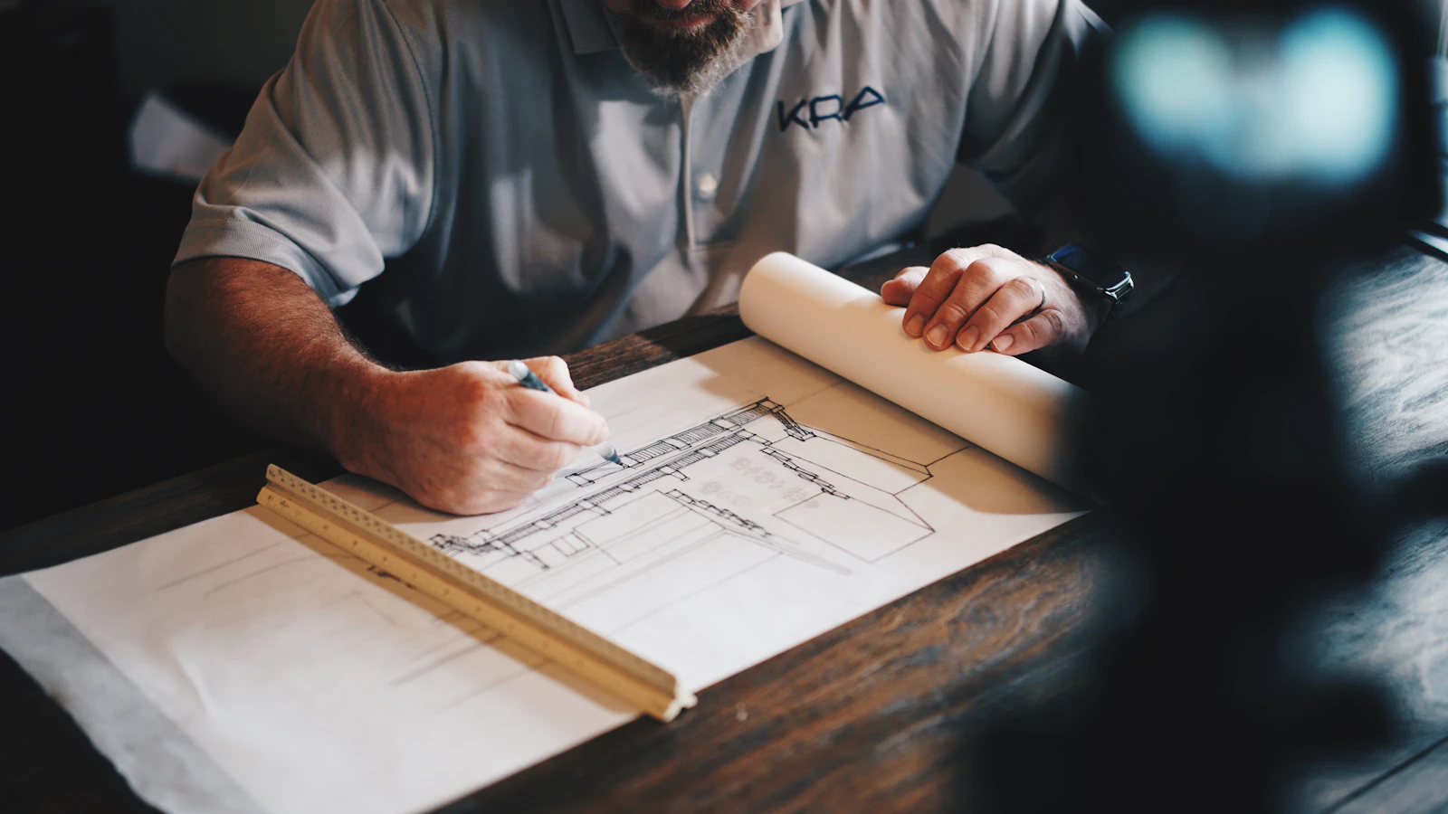 Brace, plumb, then pegPhoto: Unsplash
Post and Beam Truss Calculator Workflow
- Set units to Imperial and load the King Post preset — or open the preloaded model above.
- Apply loads at the joints: a 2 kip apex load is a realistic snow-pocket stand-in for a 16 ft frame.
- Press Calculate Forces and read minus as compression, plus as tension.
- Cross-check intuition: heels and tie beam take the tension story, rafters take compression.
- Hand the forces to a licensed timber engineer for member sizing and connection design.
Timber Frame Trusses FAQ — Sizing, Spans and Joinery
How big should a timber frame king post truss be?+
For a 12–18 ft span, published practice starts around 8×8 in posts, an 8×8 to 8×10 in tie beam, and 4×8 to 5×8 in principal rafters. From 18–24 ft the same tables step up to roughly 8×8–10×10 in posts, an 8×10–10×12 in tie beam, and 4×10–6×10 in rafters. A 16 ft king-post frame involves about six major joints — two heels, the apex, the post foot and two struts. Treat those as starting points: species, snow load and spacing all move the numbers, so have a licensed engineer confirm the final sections.
Can I use a timber frame truss calculator for glulam members?+
Yes, with one caveat. A pin-joint truss analyzer computes axial force from geometry and loads alone — species and grade do not enter that step, so the forces it reports for a sawn king post apply unchanged to a glulam one. What changes is capacity: a 24F-1.8E glulam carries an allowable bending stress of about 2,400 psi with E ≈ 1.8×10⁶ psi, roughly twice the stiffness of typical sawn framing lumber, so it deflects about half as much on the same span. Use the calculator for forces; use your engineer and the supplier's grade stamp for sizes.
What span can a hammerbeam truss cover?+
Hammerbeam framing is built for grand-hall spans of 30 ft and beyond, because it replaces the continuous tie beam with arch action through stepped hammerbeams. The surviving 14th-century English roofs prove the ceiling: Westminster Hall's hammerbeam roof spans about 68 ft. For modern residential and event-hall work, published practice mostly sits between 30 and 45 ft, with engineered projects passing 50 ft when concealed steel knife plates take the tension the missing tie beam would have carried. Below roughly 30 ft, a queen post usually delivers the same span with about a third of the joinery.
Is post and beam the same as timber frame?+
They are siblings, not twins — both build in heavy timber, but the joints differ. A true timber frame connects members with hand-cut wood-to-wood joinery: mortise-and-tenon closed by 1–1.5 in oak pegs, shouldered bearing surfaces, and draw-bored holes that pull the joint tight. Post and beam is the broader category: the same chunky members, but often joined with steel plates, bolts and concealed timber connectors. The distinction matters structurally — pegged joints behave semi-rigidly, while bolted connections sit closer to true pins, which changes how rotation and moments travel through the frame.
How do pegged joints carry tension?+
In two stages. Compression needs no help: the tenon's shoulder bears directly on the mortise, transferring load through wood-to-wood bearing. Tension is the peg's job — the tapered step and shoulders close up, and the oak peg, typically 1–1.5 in diameter, works in double shear across the 6–8 in wide tenon. Draw-boring (offset-drilling the mortise hole slightly toward the shoulder) pre-tensions the joint so it stays tight as the timber seasons. The governing limit is usually the tenon's cross-section in shear rather than the peg itself — which is why joint geometry, not peg count, drives capacity.
Do timber frame trusses need steel plates?+
Traditionally, no — a well-cut frame from 12 to 24 ft carries entirely on wood: mortise-and-tenon, pegs, and bearing surfaces. Modern engineering adds steel where the numbers demand it. Common moves include slotted-in knife plates at heel joints on spans past 30 ft, flitch reinforcement of a tie beam carrying suspended floor loads, and concealed steel gussets inside hammerbeam transitions. A useful rule from practice: the moment a design calls for tension in a member the joinery was never shaped to resist — a hammerbeam's wall posts, for example — steel appears in the drawing. Your engineer decides; the tradition just sets the default.
🧭 Where to go next on this site
Run the heavy-timber model from the home page free analyzer, browse every tool in the calculators hub, or keep reading on the guides hub. For the profile in this guide, the King Post Truss Calculator and the Truss Analysis Calculator are the direct routes — and if your job is actually the light factory-built kind, the prefab roof trusses guide is its counterpart.
Related Guides & Calculators
Scissor Truss Calculator
Scissor truss calculator for cathedral ceilings: check interior clearance vs wall thrust, see truss depth effects, and compare spans before you build.
Attic Truss Calculator
Attic truss calculator with a room-in-truss size chart: usable room width and height by span, chord load differences, and bonus room planning data.
Gambrel Truss Calculator
Gambrel truss calculator: the two-slope angle method, section lengths, barn roof height by span, and a full 12 ft gambrel roof example.
Roof Truss Design Calculator
Roof truss design calculator and build-your-own workflow: pick a type, set span and pitch, run member forces, and hand clean numbers to your supplier.
Shed Roof Truss Calculator
Shed roof truss design calculator for mono pitch and lean-to roofs: one-slope geometry, wall connection checks, and a full 12 ft shed worked example.
Floor Truss Calculator
Floor truss calculator for open-web and flat truss design: depth-vs-span tables, L/360 deflection checks, plumbing routing wins, and a preloaded model.
Steel Truss Calculator
Steel truss calculator for metal truss design: set E = 29,000 ksi, compare steel vs wood member forces on the same frame, and use the section-area table.
Bridge Truss Calculator
Bridge truss calculator with one-click Pratt, Howe and Warren models: same load, three force tables, and classroom-ready comparison steps.
Truss Analysis Calculator
Free 2D truss analysis calculator with steps: model any truss, solve reactions, displacements and member forces, and audit the full stiffness report.
Truss Load Calculator
Truss load calculator that converts psf roof loads into joint point loads: tributary width, dead, live and snow values, worked examples, and deep-linked models.
Roof Truss Span Calculator
Roof truss span calculator: turn span and pitch into truss length, ridge height, and angle — with 4/12 and 6/12 quick examples and plumb cut angles.
Truss Cost Calculator
Truss cost calculator: price ranges by span and pitch, weight and delivery estimates, labor factors, and the spec list to send manufacturers.
Truss Spacing Calculator
Truss spacing calculator: 16 vs 24 inch on-center logic, the truss count formula, load-span-spacing limits, and rafter spacing comparisons.
Roof Truss Calculator Metric
Free metric roof truss calculator for UK, Australia, NZ & Canada: span, pitch in degrees, truss length and height in mm, with C24/MGP10 timber notes.
Rafter Length Calculator
Free rafter length calculator: turn span, pitch and overhang into rafter length, plumb cut angle and birdsmouth seat cut, with 4/12-12/12 tables.
King Post Truss Calculator
King post truss calculator: preload a 16 ft model, hand-check member forces, size the post, and see span-to-rise rules and curved-bottom variants.
Method of Joints & Sections — How to Calculate Truss Forces
Learn to calculate truss forces by hand: the method of joints rule set, two fully worked examples, a method of sections shortcut, a printable truss calculations worksheet, and stress-ratio strength checks — each verifiable in the free calculator.
Roof Truss Types — Parts, Names & Anatomy Explained
A visual encyclopedia of roof truss types: King Post, Queen Post, Fink, Howe, Pratt, Warren, Scissor, Gambrel, Attic, Mono, Parallel Chord, Girder and A-Frame — each with a diagram, span range, strengths and watch-outs, plus a parts-of-a-truss glossary.
Common Truss Sizes — Charts by Span (12–40 ft)
A quantified reference for common truss sizes: a master chart from 12 ft to 40 ft spans with chord sizes (2x4 vs 2x6), web configurations, spacing and applications, plus per-span detail blocks and a truss count calculator.
Prefabricated Wood Roof Trusses — How They're Made & Ordered
The only factory-side guide on this site: how prefabricated wood roof trusses are manufactured — design software, jigs, hydraulic plate presses, engineered lumber — plus the custom-truss ordering workflow, typical lead times, and the questions to ask roof truss manufacturers before you order.
Pole Barn Trusses — Post-Frame Truss Design & Spacing
An application guide to pole barn trusses: why post-frame buildings use wide 8-foot truss spacing, steel vs wood comparisons, ready-to-model 30 ft and 40 ft barn truss schemes with deep links into the calculator, and the full purlin-and-truss layout sequence from pole to ridge.
PLTW 2.1.7 Calculating Truss Forces — Worked Walkthrough
A methodology-first walkthrough of PLTW POE Activity 2.1.7 calculating truss forces: reaction steps, joint-by-joint equilibrium on a 30° Warren truss with a 1 lb center load, section-cut verification, and a five-test answer-checking routine — every number reproducible in the free calculator.
Truss Calculation Software Compared: Excel, MATLAB, SkyCiv
A scenario-based comparison of truss calculation software: browser calculators for quick force checks, Excel templates for repeated geometry, MATLAB and Python scripts for batch studies, MDSolids for coursework, and SkyCiv, Medeek, MiTek or ETABS for engineered and manufactured work.
Try the Free Calculators
Scissor Truss Calculator
Scissor truss calculator for cathedral ceilings: check inter...
Attic Truss Calculator
Attic truss calculator with a room-in-truss size chart: usab...
Gambrel Truss Calculator
Gambrel truss calculator: the two-slope angle method, sectio...
Roof Truss Design Calculator
Roof truss design calculator and build-your-own workflow: pi...
Shed Roof Truss Calculator
Shed roof truss design calculator for mono pitch and lean-to...
Floor Truss Calculator
Floor truss calculator for open-web and flat truss design: d...
Steel Truss Calculator
Steel truss calculator for metal truss design: set E = 29,00...
Bridge Truss Calculator
Bridge truss calculator with one-click Pratt, Howe and Warre...
Truss Analysis Calculator
Free 2D truss analysis calculator with steps: model any trus...
Truss Load Calculator
Truss load calculator that converts psf roof loads into join...
Roof Truss Span Calculator
Roof truss span calculator: turn span and pitch into truss l...
Truss Cost Calculator
Truss cost calculator: price ranges by span and pitch, weigh...
Truss Spacing Calculator
Truss spacing calculator: 16 vs 24 inch on-center logic, the...
Roof Truss Calculator Metric
Free metric roof truss calculator for UK, Australia, NZ & Ca...
Rafter Length Calculator
Free rafter length calculator: turn span, pitch and overhang...
King Post Truss Calculator
King post truss calculator: preload a 16 ft model, hand-chec...