🎓 PLTW 2.1.7 Calculating Truss Forces — Worked 30° Walkthrough
Interactive Solver — 30° Warren Truss, 1 lb at Top Center
A 16 ft Warren bridge with 2 bays, step through every equilibrium equation exactly the way Activity 2.1.7 grades it — no software needed.
Model the truss and find the support reactions
- Warren bridge: 16 ft span, 1.54 ft tall, 2 bays. Bottom joints at 0, 5.33, 10.67 and 16 ft; top joints at 2.67, 8 and 13.33 ft — every diagonal meets the deck at 30° (tan⁻¹ of 1.54 ÷ 2.667).
- Determinacy check: 11 members + 3 reactions = 14 = 2 × 7 joints ✓ statically determinate.
- Pin at the left end, roller at the right. One 1 lb load straight down at the top-center joint. ΣM about the pin: 1 × 8 − G·16 = 0 → G = 0.5 lb ↑.
- ΣFy: A + G = 1 → A = 0.5 lb ↑. ΣFx: Ax = 0 — the roller carries no horizontal force, and symmetry confirms the 50/50 split.
What Activity 2.1.7 Calculating Truss Forces Asks You to Do
PLTW Principles of Engineering puts 2.1.7 Calculating Truss Forces at the exact spot where the statics unit stops being vocabulary and starts being arithmetic. Activity 2.1.6 hands you the recipe — the steps for calculating truss forces: confirm the truss is determinate, find the support reactions, solve the joints. Activity 2.1.7 then hands you truss drawings with real dimensions and point loads and asks you to run that recipe until every single member carries a number and a label: tension or compression.
Most course versions of the worksheet follow the same shape. You get one or two statically determinate trusses — often drawn with 30°, 45° or 60° angles so the trigonometry stays clean — a stated point load in pounds or newtons, and a member-force table to fill with signed values. Some teachers split the activity into part 1 and part 2, where the second part adds a second load, a second truss shape, or loads hung from bottom-chord joints. Some learning-management exports abbreviate the title to A2.1.7 or a217. Whatever the packaging, the graded artifacts are identical.
- ▸A determinacy check: members plus reactions must equal twice the joint count, m + r = 2j, before any solving starts.
- ▸Support reactions written with the equilibrium equations that produced them — not just the final numbers.
- ▸A member table with a signed force for every member, labeled T or C, consistent with one stated convention.
- ▸Conclusion answers in full sentences that explain why the forces distribute the way they do.
The solver above is your map for the rest of this page. It solves a 16 ft Warren bridge — 1.54 ft tall, 2 bays, every diagonal at 30° — carrying a single 1 lb point load at the top-center joint. Every equation is visible, every number re-derivable by hand, and the same seven-step march you see there is the same march your worksheet grades. The sections below unpack the method behind the steps, extend it to double-inverted and popsicle-stick builds, and then cover the mistakes and the worksheet workflow that separate full-credit submissions from half-credit ones.
The Three-Step Method: Reactions, Joints, Sections
If you search for the unit 2.1.6 steps for calculating truss forces, every version of the lesson collapses to these same three moves in this same order. Activity 2.1.6 teaches them; 2.1.7 makes you execute them on real geometry. Learn them once here and the worksheet becomes a checklist instead of a puzzle.
Step 1 — Support Reactions From Whole-Truss Equilibrium
Freeze the entire truss into one rigid body and write three equations: the sum of moments, the sum of vertical forces, and the sum of horizontal forces. Take moments about the pin support — its two unknown reaction components pass through the pivot and drop out, leaving one equation in the roller’s single unknown. For the walkthrough truss: 1 lb × 8 ft − G × 16 ft = 0, so G = 0.5 lb upward; vertical equilibrium then gives A = 0.5 lb, and horizontal equilibrium gives Ax = 0. When the truss and the load are symmetric, state the symmetry argument and predict the 50/50 split before computing — graders consistently award credit for the reasoning, and it doubles as an instant error check.
Step 2 — The Method of Joints, Two Equations at a Time
A pin-jointed joint carries no moment, so each joint offers exactly two equations: ΣFx = 0 and ΣFy = 0. Two equations solve two unknowns, which is why the entry joint matters — start where a support reaction is already known and at most two member forces are not. Assume every unknown is tension (pulling away from the joint) before solving; a negative result then announces compression instead of an error. March joint to joint, feeding each solved force forward as a known, and finish at a joint where everything is already resolved so the equations close as a pure verification. In the walkthrough the march runs A → B → C → D, and symmetry hands over the right half for free.
Step 3 — The Method of Sections as the Final Check
One imaginary cut through no more than three unknown members isolates a free body with three equations — ΣFx, ΣFy and ΣM — enough to solve all three cut forces in a single pass. The superpower is the moment equation: pivot about the panel point where two of the three unknowns pass through, their moment arms go to zero, and the third force falls out of one line of arithmetic. On the walkthrough truss, cutting through the top chord, the center web and the center bottom chord and pivoting about the top-center joint gives 0.5 × 8 = 4.0 lb·ft, and dividing by the 1.54 ft truss height certifies the biggest member force on the page: 4.0 ÷ 1.54 = 2.597 lb of tension. Run this check on your worksheet’s largest chord before you submit — it is the cheapest independent verification available.
Worked Example: 30° Warren Truss with a 1 lb Point Load
Here is the full joint-by-joint derivation behind the solver, in prose, with every number traceable. The model: a Warren bridge spanning 16 ft, standing 1.54 ft tall, with 2 bays. Bottom joints sit at 0, 5.333, 10.667 and 16 ft; top joints alternate at 2.667, 8 and 13.333 ft. Seven nodes total, eleven members. Every diagonal rises 1.54 ft over a 2.667 ft half-panel, and tan⁻¹(1.54 ÷ 2.667) = 30.0° — so sin = 0.500 and cos = 0.866 on every web. The supports are a pin at the left end and a roller at the right end, and one 1 lb load acts straight down at the top-center joint. Determinacy: 11 members + 3 reactions = 14 = 2 × 7 joints, statically determinate, solvable by equilibrium alone.
Reactions — 0.5 lb at each support
Moments about the pin: the 1 lb load acts 8 ft from the pin, so 1 × 8 − G × 16 = 0 and G = 0.5 lb up. Vertical equilibrium: A + 0.5 = 1, so A = 0.5 lb up. Horizontal equilibrium: Ax = 0, since no horizontal load exists and the roller cannot supply one. Two reactions, both 0.5 lb — the symmetry shortcut confirmed by computation.
Joint A — end post and first bottom chord
Two members meet the pin: end post A–B climbing at 30° and bottom chord A–C running horizontal. Vertical equilibrium: 0.5 + F_AB × 0.500 = 0, so F_AB = −1.000 lb — compression, the end post pushing down on the support. Horizontal equilibrium: F_AC + (−1.000) × 0.866 = 0, so F_AC = +0.866 lb — tension, the bottom chord restraining the support from sliding outward.
Joint B — web tension and top-chord compression
The compressed end post pushes joint B up-slope: 0.866 lb horizontal, 0.500 lb vertical. Vertical equilibrium: 0.500 − F_BC × 0.500 = 0, so F_BC = +1.000 lb of tension in the web. Horizontal equilibrium: 0.866 + 1.000 × 0.866 + F_BD = 0, so F_BD = −1.732 lb — compression in the first interior top chord. The 1.732 is exactly 2 × 0.866: the top chord catches the end post’s push and the web’s pull in one member.
Joint C — the center bottom chord emerges
At the first interior bottom joint, web B–C (+1.000) pulls up-left and chord A–C (+0.866) pulls toward the support. Vertical equilibrium: 0.500 + F_CD × 0.500 = 0, so F_CD = −1.000 lb — the center web works in compression. Horizontal equilibrium: −0.866 − 0.866 − 0.866 + F_CE = 0, so F_CE = +2.598 lb with three-decimal trigonometry — and +2.597 lb from the exact section cut in the next step. The 0.001 difference is pure rounding of the 1.54 ft height; quote +2.597 lb or +2.60 lb and any grader is satisfied.
Joint D — the loaded joint closes the left half
The top-center joint gathers the 1 lb load, compressed top chord B–D and compressed web C–D from the left. The two mirrored members on the right share the load exactly: vertical equilibrium reads 0.500 + 0.500 − 1.000 = 0, and horizontal equilibrium reads +1.732 − 1.732 + 0.866 − 0.866 = 0. So D–F = −1.732 lb and D–E = −1.000 lb, completing the left half with zero residuals.
Mirror, then certify with the section cut
Load, geometry and supports are all mirror images, so joints E, F and G replay C, B and A: web E–F = +1.000 lb, end post F–G = −1.000 lb, chord E–G = +0.866 lb. The independent check: cut through B–D, C–D and C–E, keep the left body, and take moments about the top-center joint — both other cut members pass through it, so only the reaction and the center bottom chord have arms. 0.5 × 8 = 4.0 lb·ft, and 4.0 ÷ 1.54 = +2.597 lb of tension, matching the joint march. Eleven members, three reactions, no leftovers.
| Member(s) | Role | Force | State |
|---|---|---|---|
| A–B, F–G | End posts (support to first top joint) | −1.000 lb | Compression |
| B–D, D–F | Interior top chords (both meet the loaded joint) | −1.732 lb | Compression |
| C–D, D–E | Webs adjacent to center | −1.000 lb | Compression |
| A–C, E–G | Bottom chords, end panels | +0.866 lb | Tension |
| C–E | Bottom chord, center panel (4.0 ÷ 1.54) | +2.597 lb | Tension |
| B–C, E–F | Webs adjacent to supports | +1.000 lb | Tension |
 Warren diagonals at work under a deck loadPhoto: Unsplash
Reading the table like an engineer
- ▸The center bottom chord is the biggest force on the page — 2.597 lb against 0.866 lb in the end panels, a factor of three. That is the beam analogy: chord force = moment ÷ height, and midspan is where the moment peaks.
- ▸Everything above the deck works in compression and everything along the deck works in tension — the signature of a truss behaving as a deep beam.
- ▸Forces scale linearly: hang 5 lb at the same joint and the whole table multiplies by five, so 0.5 lb reactions become 2.5 lb and the center chord reaches about 13 lb.
💡 The one-liner worth memorizing: bottom-chord force = moment ÷ truss height. For this model the midspan moment is 0.5 × 8 = 4.0 lb·ft and the height is 1.54 ft, so the center chord must carry 2.597 lb no matter how you solve it. When your worksheet truss is taller, chords calm down; when it is shallower, they scream. That single relationship explains most of the numbers any 2.1.7 key will show.
Double Inverted Truss & Popsicle Bridge Force Estimates
Two builds show up constantly once a class moves past the worksheet: the double inverted truss, where two truss planes mirror each other around a shared deck, and the popsicle-stick bridge that has to survive a loading day. Neither needs new theory — both are the same three-step method plus one bookkeeping decision about how the load splits.
How to Approach a Double Inverted Truss
A double inverted truss looks intimidating because the drawing has twice as many members, but the analysis trick is to treat it as two ordinary plane trusses stacked in parallel. Start with the load path: the deck collects the applied load and delivers it to the two truss planes through their connection points. When the load sits on the centerline and the two planes are identical mirror images, symmetry splits it evenly — half of every deck load goes to each plane, exactly as the 1 lb in the walkthrough would become 0.5 lb per plane. Then solve one plane as a standard two-dimensional truss: reactions, joint march, section check. Mirror the results across the deck and the second plane is done without a single additional equation.
Three cautions keep the shortcut honest. First, count determinacy per plane — each plane must satisfy m + r = 2j on its own before the mirror trick applies. Second, the transverse members connecting the two planes carry almost nothing under a perfectly symmetric gravity load, but they are not decorative: they brace the planes against sway and wind, so they belong in the build even when the calculation shows them idle. Third, if the load sits off the centerline, the 50/50 split dies — the deck then behaves like a small beam spanning between the two planes, and you need its equilibrium to find the real distribution before either plane can be solved.
Force Calculations for a Popsicle Truss Bridge
A popsicle truss bridge is analyzed with exactly the member table from the worked example — then the numbers get mapped onto how sticks actually fail. Tension members fail at the stick itself or, far more often, at the glue joint: test one stick with a hanging bucket to get its tensile capacity, and treat the gusset area as the real bottleneck, because a 1 square inch of sloppy hot-glue fails long before the wood does. Compression members fail by buckling, which depends on length: test a full-length stick as a column and compare it against a half-length one — the shorter, braced stick carries dramatically more, which is why real designs add mid-panel bracing to long compression chords.
The walkthrough table then becomes a reinforcement map. Because forces scale linearly, multiply every entry by your total deck load: with 10 lb total, the reactions become 5 lb each and the center bottom chord carries roughly 26 lb while the end panels carry about 8.7 lb. That three-to-one ratio is the design insight — if the end panels get one stick, the center panel deserves three, and the top chords with their 1.732 lb rating get two. Finish with the cheapest sanity check in statics: weigh the bridge, add the applied test load, and confirm the support reactions your model predicts actually match what the scales show on loading day. If the totals disagree, the load path in your model is not the load path in the build.
Scaling the worked table to your build
- ▸Reactions: half the total load each, provided the load stays centered — 10 lb total → 5 lb per support.
- ▸Center bottom chord: 2.597 × load — the member to double up first.
- ▸Top chords: 1.732 × load, all compression — buckling checks apply before stress checks.
- ▸End posts and webs: 1.000 × load each — lightest duty, but the end posts also land the reaction directly.
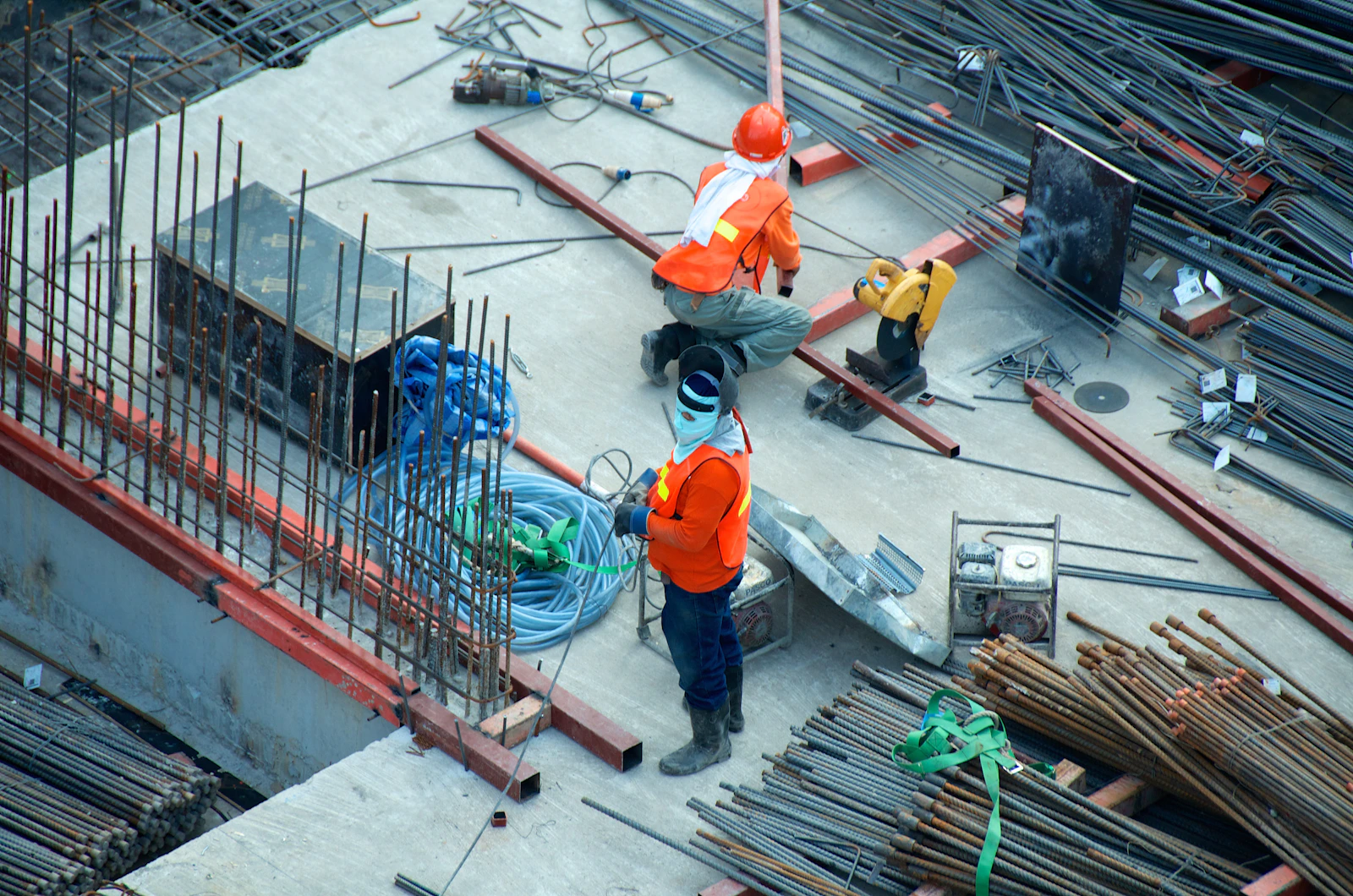 Sketch, solve, then buildPhoto: Unsplash
Checking Your Answers with the Free 30 Degree Truss Calculator
The free calculator on this site runs the same equilibrium mathematics as your hand work — reactions, joint equilibrium, member forces — just executed by a stiffness solver instead of a pencil. That makes it a verification tool, not a replacement for the method: graded work needs your equations on paper, and the calculator needs your finished table to compare against. A 30 degree truss with 1 lb point load calculation like the walkthrough above checks out in under a minute: open the preloaded model, press Calculate Forces, and read the table member by member against your worksheet.
Compare in this order: reactions first (they are one decimal each, and a mismatch there poisons everything downstream), then the largest member forces, then signs. Two conventions to know while comparing — the tool takes positive vertical load input as downward, matching the way gravity loads act, and its member table labels tension and compression explicitly, so a hand table of +tension/−compression lines up directly. If one member disagrees by a small amount, suspect early rounding of sin and cos; if everything disagrees, suspect a reaction.
Open the free calculator preloaded with this exact 30° Warren model
Span 16 ft, height 1.54 ft, 2 bays, 1 lb at top center — identical to the walkthrough. Every number in the results table above should match the tool line by line, including the 2.597 lb center chord.
Launch preloaded model →Pratt bridge model for the 2.1.8-style comparison
When the unit moves from calculating forces to judging designs, this 16 ft, 4-bay Pratt bridge is the sandbox: same workflow, taller profile, more bays — and a nice contrast against the Warren for a design-comparison write-up.
Launch preloaded model →Why the tool agrees to the last decimal: both your worksheet and the solver enforce the same two conditions — every joint is in equilibrium and every member carries pure axial force. Agreement is not luck; it is the definition of a statically determinate truss. Disagreement, when it happens, is a feature: it points at the exact line where a sign, a mode setting, or a reaction slipped.
Common Mistakes That Cost Points
Every item below is a real deduction pattern from graded truss work. None of them are about being bad at math — they are bookkeeping slips that a thirty-second habit would have caught.
❌ Don’t: Flipping the sign convention halfway through
Pick one rule and keep it: assume every unknown member force is tension (pulling away from the joint). A positive answer confirms tension; a negative answer means compression. If your worksheet expects compression written as negative — and 2.1.7 almost always does — a table of positive magnitudes loses the physics even when every number is arithmetically right.
❌ Don’t: Mixing degrees and radians on the calculator
tan⁻¹(1.54 ÷ 2.667) = 30.0°, which is 0.524 radians. Solve in the wrong mode and cos 30° comes out 0.154 instead of 0.866, and every joint after the first inherits the error. The five-second check: type sin 30 and confirm the display reads exactly 0.5 before you trust any trig that session.
❌ Don’t: Inventing a horizontal reaction at the roller
A roller supports one direction only — vertical here. Only the pin carries a horizontal reaction, and with no horizontal applied load the pin's Ax is simply zero. Writing a second horizontal reaction makes the truss indeterminate on paper (m + r > 2j) and no joint march will ever close.
❌ Don’t: Treating compression as positive when the worksheet wants negatives
Some textbooks label compression with a C and move on; the 2.1.7 convention is signed values with tension positive. If you solved with a compression-positive habit, your table will show +1.732 where the key shows −1.732. Convert at the end, and state the convention in one line so the grader sees the choice was deliberate.
❌ Don’t: Entering the joint march at a three-unknown joint
Each joint gives you exactly two equations, so a joint with three unknown members is a dead end. Always enter through a support joint carrying at most two unknowns — joint A in the walkthrough — and march inward. If you get stuck mid-truss, the slip is almost always a sign you carried wrong two joints back.
❌ Don’t: Rounding sin and cos too early
Keep 0.500 and 0.866 (or store full precision) until the final table. Rounding cos 30° to 0.87 looks harmless, but it drifts the third bottom chord by 0.01 and later joints by more, and graders deduct when your ΣFy = 0 check no longer closes to within a thousandth.
❌ Don’t: Letting the load drift off the joint
The method of joints only works while loads act at joints, because a pin joint resists no moment. Slide the 1 lb to mid-panel and the members pick up bending that the joint equations cannot see — the whole solution becomes invalid, not just slightly off. Redraw the load at the nearest panel point before solving.
💡 The pre-submission ritual: before handing in, confirm three things in thirty seconds — the reactions sum to the applied load, one joint’s equations genuinely close to zero, and every member row carries a sign and a T/C label. Those three checks catch the large majority of lost points before the grader ever sees the page.
Worksheet, Conclusion Questions and Answer Keys
The worksheet is where the method gets graded, and the conclusion questions are where understanding gets graded. They reward different habits, so prepare for both deliberately.
How to Answer the 2.1.7 Conclusion Questions
Graders read conclusion answers looking for four things: the method shown (equations, not just answers), units on every quantity — pounds for forces, feet for lengths — signs or T/C labels on every member, and reasoning sentences that connect a force to a member’s role. A strong answer pattern, using this page’s model as the template: state how the load reached the supports (“symmetry splits the 1 lb load into two 0.5 lb reactions”), state what the joint march produced (“compression concentrated in the top chords at −1.732 lb, tension peaking in the center bottom chord at +2.597 lb”), and state the verification (“a section cut with the moment 0.5 × 8 = 4.0 lb·ft divided by the 1.54 ft height reproduces the 2.597 lb chord independently”). Three sentences, every one carrying a checkable number, beat a paragraph of adjectives.
Using the Worksheet PDF or DOCX Responsibly
Worksheet PDFs and DOCX files exist so your work has structure — a sketch box, a reactions block, a joint table, a conclusion section. Use the blank version your teacher distributes and fill it with your own equations. Answer keys have one legitimate role: checking a completed attempt. Copying from a key defeats the skill the activity exists to build, and it shows — question sets are versioned, teachers compare work against in-class method, and a perfect table with no supporting equations is its own red flag. Sites hosting scanned PLTW answer keys are also distributing copyrighted curriculum, and their numbers frequently belong to older revisions that no longer match current worksheets.
This page deliberately teaches with its own example — a 16 ft, 30° Warren bridge with a 1 lb load — so everything here is reproducible without touching any course material. If you are stuck on a worksheet problem, the productive move is to re-run the seven steps on this Warren model until each one feels mechanical, then apply the identical moves to your truss: same determinacy check, same moment equation for reactions, same tension-positive joint march, same section-cut verification. The method transfers; the numbers stay yours.
FAQ: 2.1.7 Calculating Truss Forces
Where can I find activity 2.1.7 calculating truss forces answers?▼
The reliable source is your own teacher — PLTW distributes worksheet versions through instructors, and posted copies on random sites are frequently from older revisions or simply wrong. The durable route is to compute the answers yourself: determinacy check, reactions, joint march, sign check. This page gives you a complete 30° Warren model solved step by step so you can verify your process on identical-style numbers, and the free calculator deep link lets you check any geometry your worksheet throws at you in about a minute. Method first, numbers second — that is what actually earns the points.
How do I solve 2.1.7 calculating truss forces number 4?▼
Nobody can see your specific worksheet, but problem order almost always escalates, so by number 4 you are likely facing a load applied at a non-support joint, or a second load case. The recipe never changes: find reactions with whole-truss equilibrium (sum moments about the pin, then vertical forces), start the joint march at whichever joint has at most two unknown members, assume tension positive, and carry signed results forward. If a joint stalls with three unknowns, back up — an earlier sign slipped. Finish by verifying one member with a section cut before you write the final table.
What is different in activity 2.1 7 calculating truss forces pt 2?▼
Part 2 typically adds one layer of complexity over part 1: a second point load, a load hung from a bottom-chord joint, or a different truss shape altogether. The consequence is specific — symmetric loading let part 1 split reactions 50/50 by inspection, and part 2 usually breaks that shortcut, so the moment equation about the pin does real work. The three-step method (reactions, joints, section check) is unchanged. Watch also whether part 2 asks for force direction justification in sentences; many versions shift grading weight toward explanation at that point.
How do I solve 2.1.7 calculating truss forces question 5?▼
In most versions, later questions narrow the ask to one member or a classification rather than the whole table. If it names a single member, skip the full march and use the method of sections: cut through no more than three members including the target, keep one free body, and take moments about the panel point where the other two cut members' lines of action cross — one equation, one unknown. If it asks which members fail first, compare force magnitudes and remember compression members can buckle before stress limits matter. Either way, show the equations, not just the number.
Is there a 2.1.7 calculating truss forces answer key I should check against?▼
Check against physics before you check against any key. Five tests catch nearly every error: the determinacy count closes (m + r = 2j); reactions sum against the applied load; every solved joint's ΣFx and ΣFy genuinely equal zero; a section cut reproduces at least one chord force independently; and the signs make physical sense — top chords in compression, bottom chords in tension under gravity load. After a full attempt, the free calculator on this site is a legitimate key: preload your exact geometry and compare line by line. Your teacher's key, released after grading, is the official version.
What is A2.1.7 (a217) calculating truss forces?▼
It is shorthand for the same activity — PLTW Principles of Engineering's Activity 2.1.7 in the statics unit, compressed to A2.1.7 or a217 in some learning-management exports, class calendars, and teacher sites. The activity applies the steps taught in 2.1.6 to specific pin-jointed trusses: calculate support reactions, then member forces for every member, labeled tension or compression with correct signs. It usually precedes 2.1.8, where the unit shifts toward designing and testing. The transferable skills — equilibrium equations, trigonometry on member angles, sign discipline — are exactly what the walkthrough on this page demonstrates.
Where to Go Next on Truss-Calculator.com
Every tool and guide below is free, and each one picks up where this walkthrough stops.
Free Truss Calculator (Home)
Draw any truss, apply loads, get the full member force table.
All Calculators
The hub: roof, bridge, scissor, Warren and specialty pages.
All Guides
Method deep-dives, material guides and worked examples.
Method of Joints Guide
The generic joint-by-joint method with a printable worksheet.
Bridge Truss Calculator
Pratt, Warren and Howe bridge presets with instant forces.
Truss Analysis Calculator
Full analysis: reactions, member forces and joint displacements.
Related Guides & Calculators
Scissor Truss Calculator
Scissor truss calculator for cathedral ceilings: check interior clearance vs wall thrust, see truss depth effects, and compare spans before you build.
Attic Truss Calculator
Attic truss calculator with a room-in-truss size chart: usable room width and height by span, chord load differences, and bonus room planning data.
Gambrel Truss Calculator
Gambrel truss calculator: the two-slope angle method, section lengths, barn roof height by span, and a full 12 ft gambrel roof example.
Roof Truss Design Calculator
Roof truss design calculator and build-your-own workflow: pick a type, set span and pitch, run member forces, and hand clean numbers to your supplier.
Shed Roof Truss Calculator
Shed roof truss design calculator for mono pitch and lean-to roofs: one-slope geometry, wall connection checks, and a full 12 ft shed worked example.
Floor Truss Calculator
Floor truss calculator for open-web and flat truss design: depth-vs-span tables, L/360 deflection checks, plumbing routing wins, and a preloaded model.
Steel Truss Calculator
Steel truss calculator for metal truss design: set E = 29,000 ksi, compare steel vs wood member forces on the same frame, and use the section-area table.
Bridge Truss Calculator
Bridge truss calculator with one-click Pratt, Howe and Warren models: same load, three force tables, and classroom-ready comparison steps.
Truss Analysis Calculator
Free 2D truss analysis calculator with steps: model any truss, solve reactions, displacements and member forces, and audit the full stiffness report.
Truss Load Calculator
Truss load calculator that converts psf roof loads into joint point loads: tributary width, dead, live and snow values, worked examples, and deep-linked models.
Roof Truss Span Calculator
Roof truss span calculator: turn span and pitch into truss length, ridge height, and angle — with 4/12 and 6/12 quick examples and plumb cut angles.
Truss Cost Calculator
Truss cost calculator: price ranges by span and pitch, weight and delivery estimates, labor factors, and the spec list to send manufacturers.
Truss Spacing Calculator
Truss spacing calculator: 16 vs 24 inch on-center logic, the truss count formula, load-span-spacing limits, and rafter spacing comparisons.
Roof Truss Calculator Metric
Free metric roof truss calculator for UK, Australia, NZ & Canada: span, pitch in degrees, truss length and height in mm, with C24/MGP10 timber notes.
Rafter Length Calculator
Free rafter length calculator: turn span, pitch and overhang into rafter length, plumb cut angle and birdsmouth seat cut, with 4/12-12/12 tables.
King Post Truss Calculator
King post truss calculator: preload a 16 ft model, hand-check member forces, size the post, and see span-to-rise rules and curved-bottom variants.
Method of Joints & Sections — How to Calculate Truss Forces
Learn to calculate truss forces by hand: the method of joints rule set, two fully worked examples, a method of sections shortcut, a printable truss calculations worksheet, and stress-ratio strength checks — each verifiable in the free calculator.
Roof Truss Types — Parts, Names & Anatomy Explained
A visual encyclopedia of roof truss types: King Post, Queen Post, Fink, Howe, Pratt, Warren, Scissor, Gambrel, Attic, Mono, Parallel Chord, Girder and A-Frame — each with a diagram, span range, strengths and watch-outs, plus a parts-of-a-truss glossary.
Common Truss Sizes — Charts by Span (12–40 ft)
A quantified reference for common truss sizes: a master chart from 12 ft to 40 ft spans with chord sizes (2x4 vs 2x6), web configurations, spacing and applications, plus per-span detail blocks and a truss count calculator.
Prefabricated Wood Roof Trusses — How They're Made & Ordered
The only factory-side guide on this site: how prefabricated wood roof trusses are manufactured — design software, jigs, hydraulic plate presses, engineered lumber — plus the custom-truss ordering workflow, typical lead times, and the questions to ask roof truss manufacturers before you order.
Pole Barn Trusses — Post-Frame Truss Design & Spacing
An application guide to pole barn trusses: why post-frame buildings use wide 8-foot truss spacing, steel vs wood comparisons, ready-to-model 30 ft and 40 ft barn truss schemes with deep links into the calculator, and the full purlin-and-truss layout sequence from pole to ridge.
Truss Calculation Software Compared: Excel, MATLAB, SkyCiv
A scenario-based comparison of truss calculation software: browser calculators for quick force checks, Excel templates for repeated geometry, MATLAB and Python scripts for batch studies, MDSolids for coursework, and SkyCiv, Medeek, MiTek or ETABS for engineered and manufactured work.
Timber Frame Trusses — Heavy Timber, Glulam & Joinery Guide
A structural tour of timber frame trusses: how heavy timber differs from light prefab, the king post, queen post, hammerbeam and cruck forms with their span envelopes, glulam grades including 24F-1.8E, and the load path through mortise-and-tenon pegged joints — with a free span checker.
Try the Free Calculators
Scissor Truss Calculator
Scissor truss calculator for cathedral ceilings: check inter...
Attic Truss Calculator
Attic truss calculator with a room-in-truss size chart: usab...
Gambrel Truss Calculator
Gambrel truss calculator: the two-slope angle method, sectio...
Roof Truss Design Calculator
Roof truss design calculator and build-your-own workflow: pi...
Shed Roof Truss Calculator
Shed roof truss design calculator for mono pitch and lean-to...
Floor Truss Calculator
Floor truss calculator for open-web and flat truss design: d...
Steel Truss Calculator
Steel truss calculator for metal truss design: set E = 29,00...
Bridge Truss Calculator
Bridge truss calculator with one-click Pratt, Howe and Warre...
Truss Analysis Calculator
Free 2D truss analysis calculator with steps: model any trus...
Truss Load Calculator
Truss load calculator that converts psf roof loads into join...
Roof Truss Span Calculator
Roof truss span calculator: turn span and pitch into truss l...
Truss Cost Calculator
Truss cost calculator: price ranges by span and pitch, weigh...
Truss Spacing Calculator
Truss spacing calculator: 16 vs 24 inch on-center logic, the...
Roof Truss Calculator Metric
Free metric roof truss calculator for UK, Australia, NZ & Ca...
Rafter Length Calculator
Free rafter length calculator: turn span, pitch and overhang...
King Post Truss Calculator
King post truss calculator: preload a 16 ft model, hand-chec...